
Domain Mapping
How to map and create relations between contexts
This article will guide you through domain mapping and is divided into three sections:
Example of domain mapping
Creating domain mappings
Definition of relations
Domain mapping makes it possible to map relations between system structures/ contexts in a project. With this tool, you can map and link systems together between different contexts, thereby keeping track of any design changes made in a context, and tracking the consequences and the impact it has.
1. Example of domain mapping
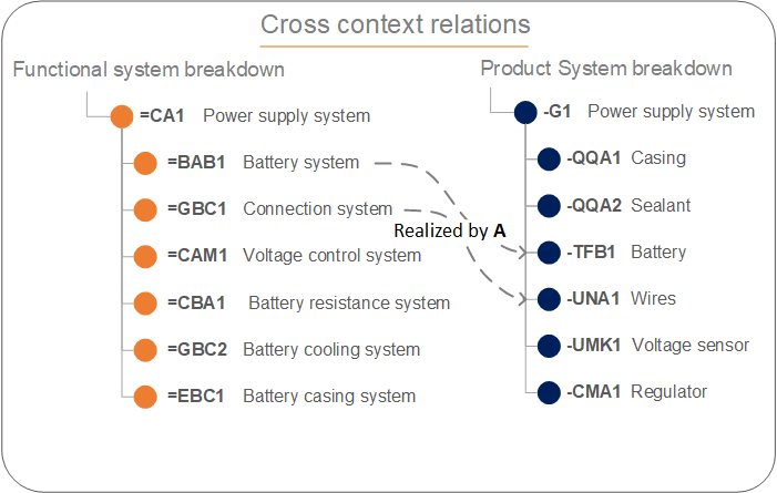
Below you can see an example of a mapping between contexts. In this example you see that =BAB1 (Battery system) in the functional systems breakdown is realized by -TFB1 (Battery system) in the product system breakdown.
Here we have mapped between two different aspect-oriented contexts. The function of the battery system is realized by this exact battery in our product structure. You can see the same link with the "Connection system" that is mapped/linked with the "Wires system".
2. Creating domain mappings
To use domain mapping you need to head into a context. Once inside:
Locate the navigation header at the top of the screen
Click on the small arrow
Tick off the contexts you want to work on
Create a mapping
Find the systems that have a relation
Hover over the system and locate the small circle
Drag the relation to the receiving system
In the right-hand sidebar locate the drop-down box
Select the correct relation
In the GIF above you can see that we give an example of =CCA1 (Battery system) which is realized by -CC1 (Battery module). We can extend the relations mapping by adding the location of the -CC1 (Battery module) as shown below.
All of this follows RDS principles and in this given example the domain relation RDS TAG looks like this:
=C1=GA1=CCA1|realized by|-U1-CC1|located in|++DAC1

Through domain mapping, we can identify functions in our functional context (=) which is realized by products in our product context (-), which then is located in the location context (+).
3. Definition of relations
The relations between two contexts differ in terms of the aspects chosen. So there are different kinds of relations e.g. from a functional (=) context to a product (-) context, product context to a location (+) context, etc. Below you can see the list of relations.
| Class | Class name | Class name direction | Examples |
|---|---|---|---|
| A | Functional allocation | Functional to product | |
| AA | Realization relation | Realized by | Complete functional allocation |
| AB | Redundant realization relation | Redundantly realized by | Complete functional allocation (Redundant) |
| AC | Partial realization relation | Partial realized by | Partial functional allocation |
| AD | Redundant partial realization | Redundantly partially realized by | Partial functional allocation (Redundant) |
| B | Spatial allocation | Location to object | |
| BA | Location relation | Hosts | Is host of |
| BB | Adjacent location relation | Is adjacent to | Is next to |
| BC | Target location relation | Is target location of | Is destination of |
| BD | Constituting space relation | Space constituted by | Space constituted by walls |
| C | Type relation | Object to type | |
| CB | Option relation | Has option | Can be type is allowed |
| CE | Type relation | Is type | Selected type |
We have more relations available if you delve into user-defined (#), object-to-process, type-to-type, process-to-process, and space-to-space relations. Contact us for more information.